


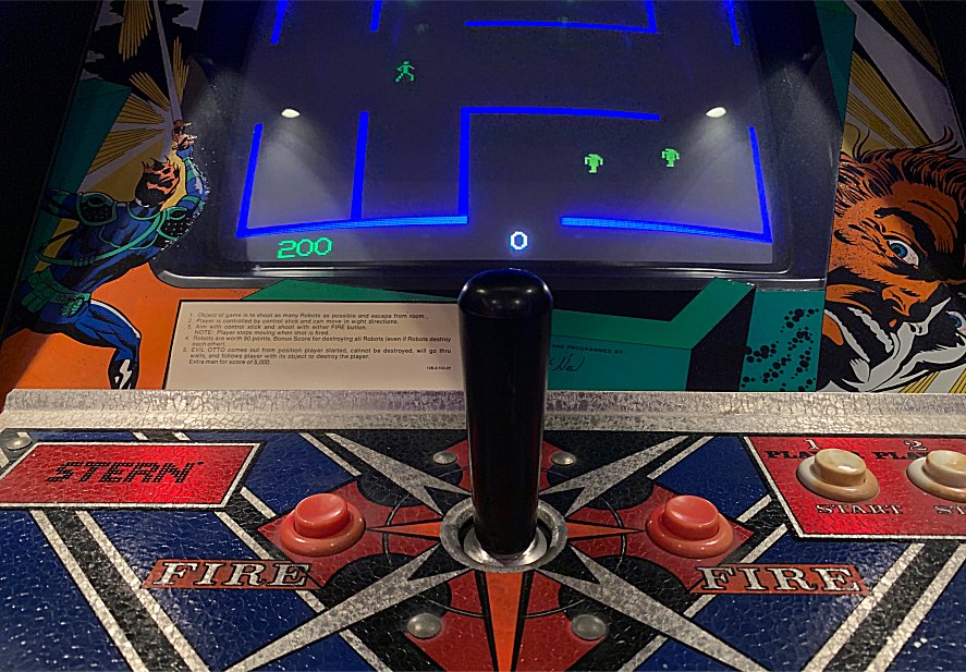
 Berzek Repair Log
|
|
| Berzek Repair Log |
    |
The game was 100% dead upon arrival.
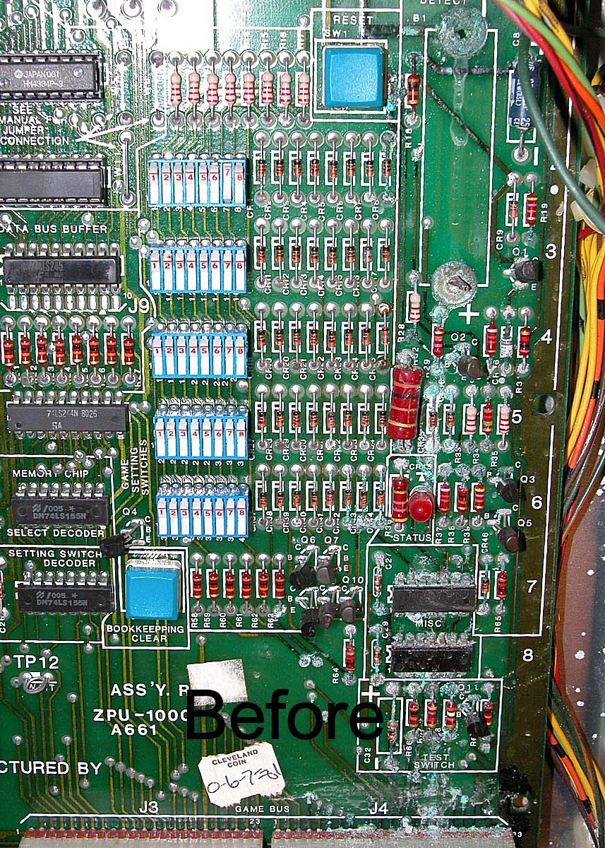
The ZPU was heavily acid damaged and produced zero 'test beeps.'
The test light on the ZPU came but just stayed on and did not
flash. It was visually obvious the reset circuit was in horrible
shape and this was confirmed when I verified pin #26 on the Z80
processor was stuck low. I neutralized all the acid damage with a
vinegar rinse and hand scrapped each individual trace to remove all of
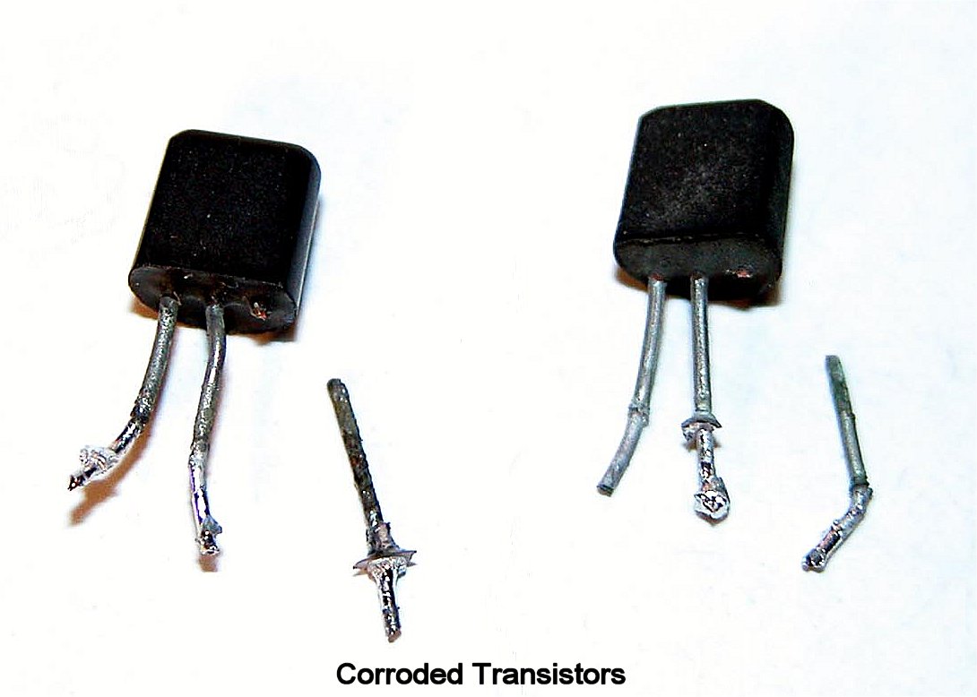
the corrosion. I replaced the 7G and 8G chips, all the transistors
in the reset circuit, a few bad diodes, and repaired many bad traces
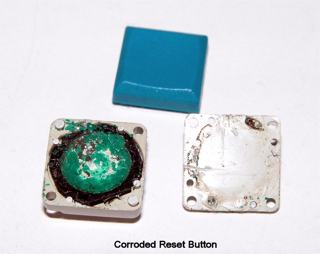
with jumper wires. The reset switch button was a corroded blob
underneath so the entire button was replaced. I cleaned the ROM's
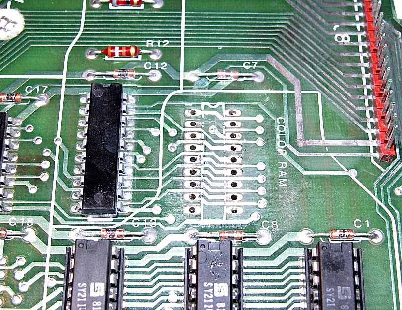
and replaced all of the socketed RAM at 1E & 2E. Be sure to use the
correct RAM depending on how your board is jumpered (mine is jumpered
at W11). I have a 2114 in the 2E position and a 6514 in the
1E position. I couldn't find 6514's for sale but 5114's work
just fine as a replacement.
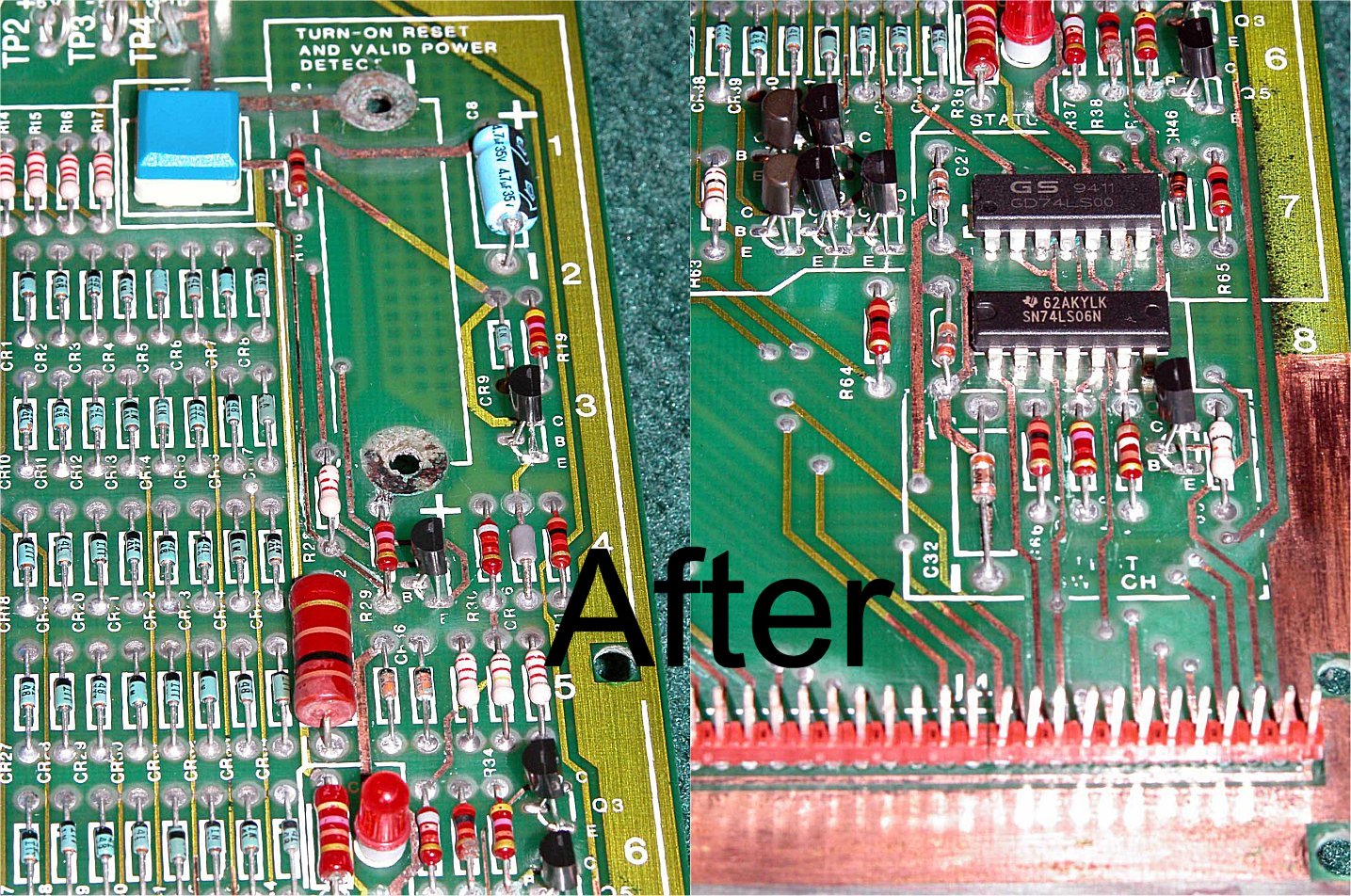
After all of these
repairs the only thing I had to show for it was the reset line now
correctly flipped from low to high upon game power up - so the reset
line was fixed! A Kester 186 flux pen was my savior when dealing
with corrosion on critical solder points. Without it the
crusty solder would not flow. The goal in a Berzerk PCB
boardset repair is to get at least 3 beeps/flashes with only the
ZPU running before hooking up any of the other boards. |
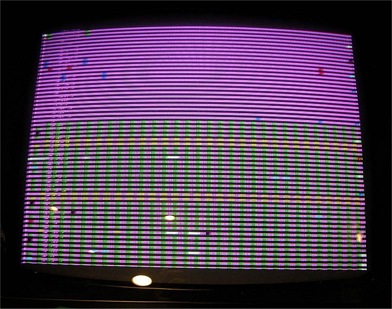 |
Low and behold after much frustration of the little red light not flashing I replaced the Z-80 and immediately got 3 flashes and 3 beeps! Flash and beep counting is very critical to determine where you are at in your repairs. After much investigation I 100% confirmed the flash/beep that occurs at game power up counts as the first flash/beep. Knowing this little tip will keep you from getting confused during your repair progress. The original Berzerk manual is a must have as it details problems associated with each of the flashes/beeps. In terms of game life I now have a rolling image on the screen that goes between a mosaic of colored garbage to a garbled version of the RAM map on the VFB. Even garbage on the screen was considered progress! Click here to see a movie of the error screen. |
 |
The next
board after the ZPU is the BSC board and it had extensive damage
as well. The 23 count header pins for the ribbon cables had
heavy corrosion and took me quite a bit of time to get it cleaned
up. Be sure to check every trace and connection....one bad
one leaves you stuck in your repair progress. I replaced all the
RAM on the BSC board and replaced a few of the sockets that were well
beyond repair. |
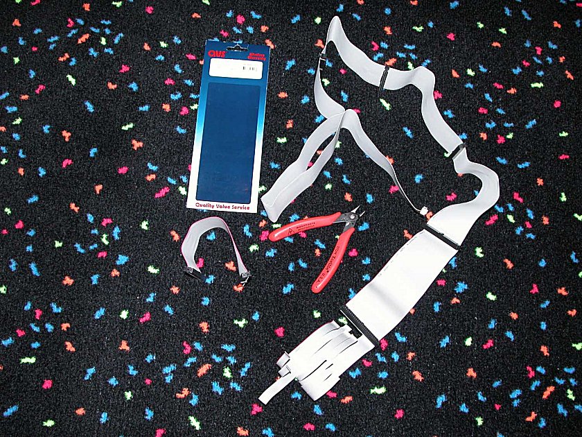 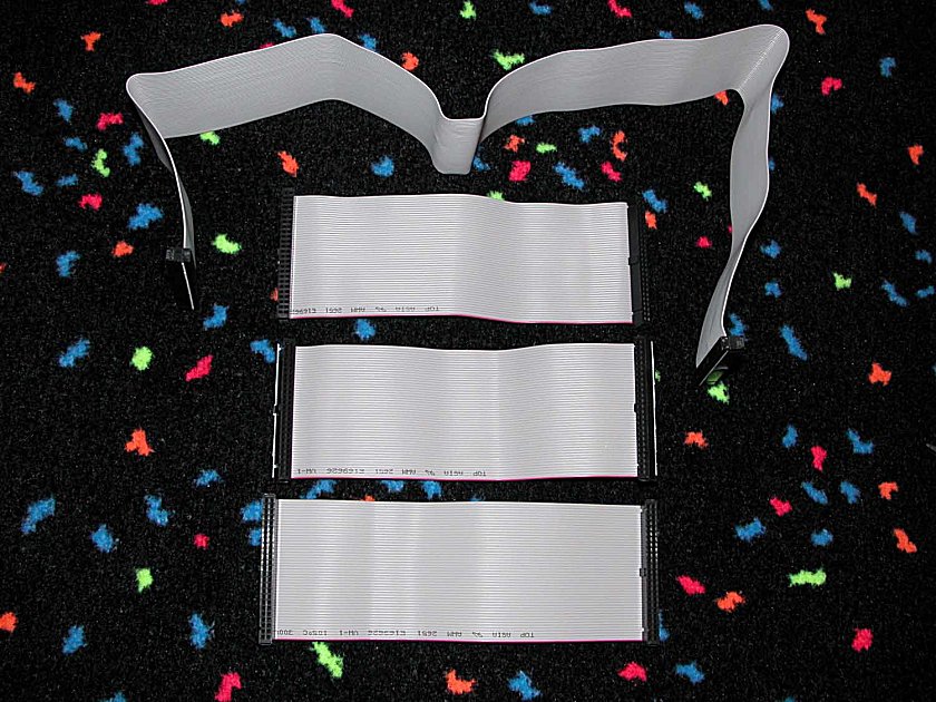 |
Interconnect cables. At this
point of the repair you almost have to assume your cables are bad
and need to be replaced. Many faulty connections are directly
traced back to bad cables. With a bright light you can actually
look into the ends of the cables and see the crimp connector spring
tabs which have failed. Another quick way to check a cable is to
shake it.....if it rattles throw it away. Replacement cables
are no longer available but I was able to find an 8 connector 50 pin
SCSI cable and cut it up to make some brand new cables! They took
a little bit of sanding on the ends to get them to mount side by side
but once they were in my confidence in the cable connection between
boards was now very high. |
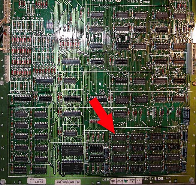 |
I started to get more test flashes/beeps after the cable repair and followed the Berzerk manual to determine that my RAM was bad on the VFB. Direct replacement RAM was not available for the sixteen 4027 RAM chips but you can replace half the amount with 4116's. I filled rows 10 and 11 with eight 4116's and it seemed to work just fine. Make sure to check for bad sockets, as they are often problematic. I found that the two chips which comprise the Arithmetic Logic Unit (ALU) at 10C & 12C (74LS181) were as bad as were their sockets. Finally, the 74LS75's located at 10D and 11D along with their sockets were bad - so be sure to check those too! All header pins on the power board were cracked and had to be re-flowed. |
 |
After all these repairs I finally had 8 flashes and 8
beeps! "Coins
Detected In Pocket!"
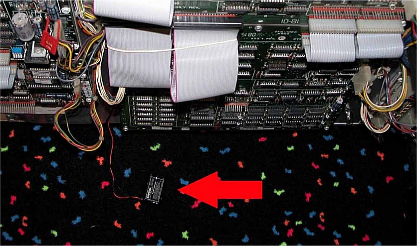
The final repair was to get the high score circuit
working by replacing the original corroded battery that ruined the ZPU
board. I used an Energizer cordless phone battery (ER-P510 -
Nickel Metal Hydride Battery) which is rated at 3.6volts and
700MAH. I soldered leads to the ZPU and remote located the
battery on the bottom of my cabinet - no more leakage down the ZPU
board! It seems to be working just perfectly and the high scores
are now saved! The total repair took me about 5-6 weeks so don't
get discouraged if this is your first or 100th attempt at repairing
this game!
|
    |
After
40 years of being chased by Evil Otto the "Humanoid" would no longer
move to the right. It
appeared that the original Berzerk optical bat joystick was in need of
repair. A
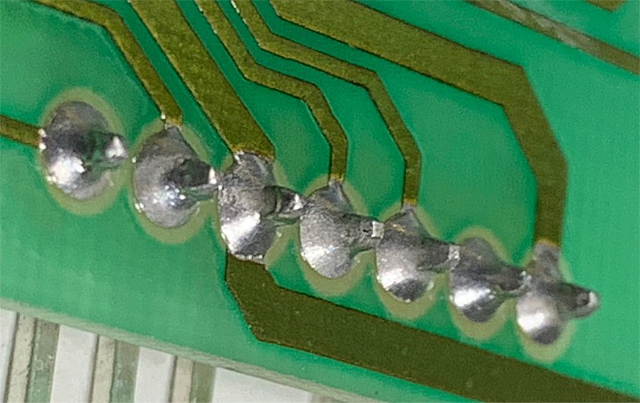
close inspection of the PRU-1000 board revealed many cracked solder
joints on the header pins. I removed all the old solder and carefully
reflowed new solder. At this time it would be a good idea to look at
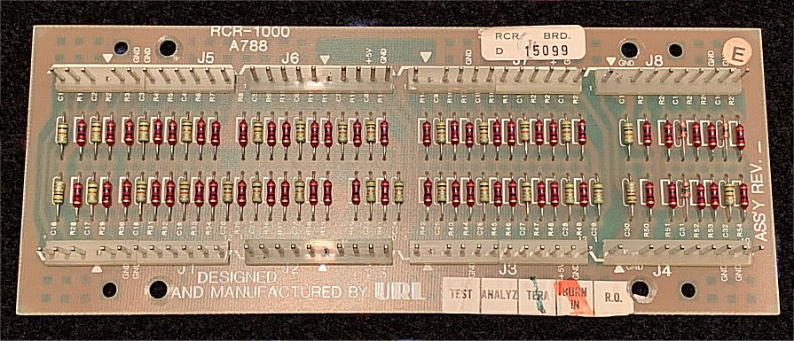
the RCR-1000 board for cracked solder and if necessary perform similar
repairs. The board is located in the lower right hand corner of the
board set as it is mounted in the game. Many times cracked or weak
solder joints will cause erratic joystick movements or in this case, no
movement at all. |
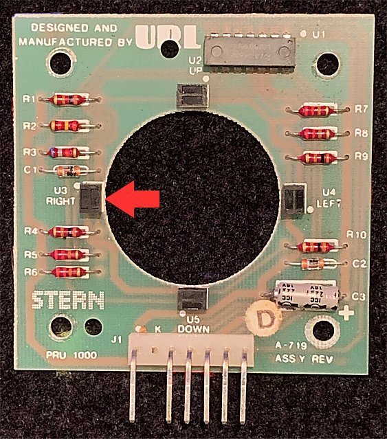  |
After
reflowing all the header pins the performance of the joystick improved
but still had no movement to the right. The next step in the repair was
to make sure the reflective side of the washer covering the opto was
clean and both were properly aligned. If the joystick still
doesn't move in the desired direction it is time to replace the opto
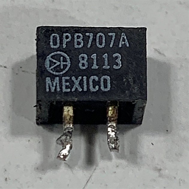
itself. I ended up replacing the opto sensor at the U3 location, which
is for right movement. The part number is OPB707A and they are
readily available online. |
 |
With
the new opto in place I once again installed the joystick and gave it a
test. Success! Evil Otto and the robots will have a much more difficult
time catching the "Humanoid" now! |
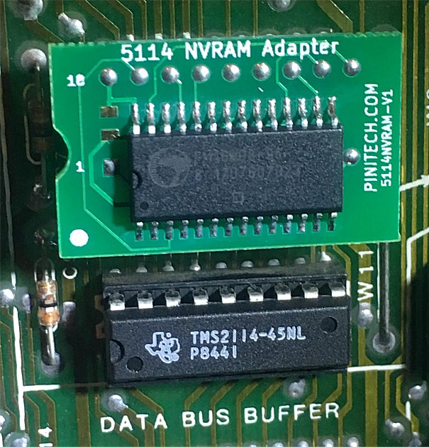 |
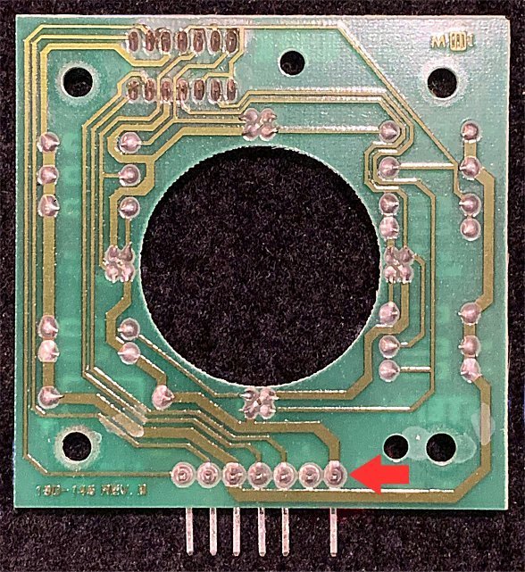
The cordless phone battery, that had
powered the high score circuit since the game was restored in 2009,
finally died. Instead of replacing the battery with another battery I
decided to go with a 5114 NVRAM module. There are several to choose
from but I selected the one from Pinitech, which is available here. The
6514 RAM is removed from 1E and the module is installed. No soldering
is required. After installation you must go into bookkeeping and zero
everything out in order for the game to operate correctly. |