


 Defender Repair Log
|
|
| Defender Repair Log |
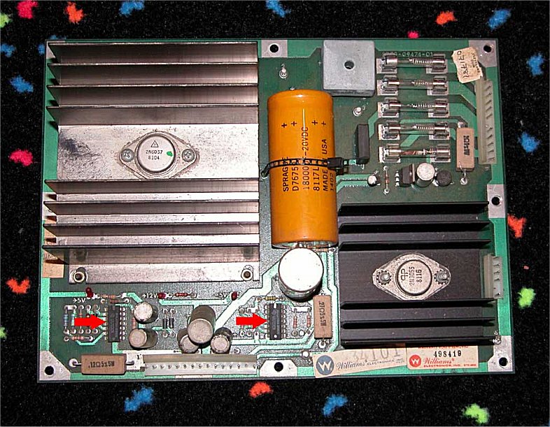 |
The game was 100% dead upon arrival. Upon close
inspection the
LED lights for the +12vdc and -5vdc on the power board were out
which indicated zero output. I cleaned the very dirty fuse holder
but that didn't solve the problem.
I also repaired many cracked solder joints on the board but the LED's
remained out. Both voltage
regulator LM723's were checked with a logic probe and it was confirmed
that heir outputs were dead. As indicated by the red arrows in
the
picture, both
voltage regulators were replaced and the +12vdc and -5vdc were
now present!
|
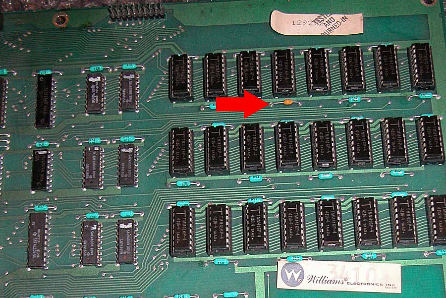 |
With the power supply board up and running the game
still did
nothing. I discovered the bank of 4116 RAM on the main CPU board
was missing the +12vdc. The power board and harness were
checked and found to be good. After an extensive search a 0.1uf
capacitor at C22 was found to be dead shorted to ground. The
capacitor, indicated by the red arrow, was replaced
and the bank of
4116 RAM was now buzzing along.
|
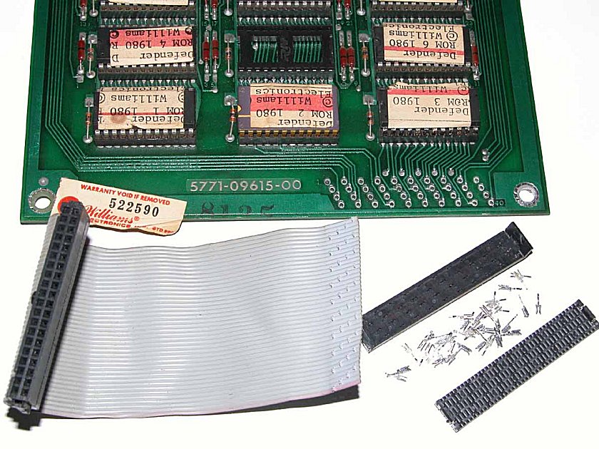 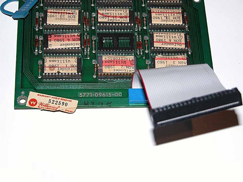 |
The game still was not booting and the interconnect
cable from the ROM
board was dropping out multiple signals including the PSO signal.
A replacement cable repair kit is available so I ordered one and
installed
it. There are many pins and solder pads to deal with during this
repair so I recommend if you attempt it...be sure to have patience
as you go. The first picture shows the old brittle cable removed
and the 1000 solder pads (Mom told me a million times never to
exagerate!) cleaned up. The second picture shows the new cable
soldered in and ready to go!
|
  |
At this point everything seemed to be working but I
still had a blank sceen and no sound to indicate that the game was
at
least playing blind. On to the WG4600 monitor. There were
the typical cracked solder joints everywhere but even after the
repair...no picture. It turns out my 'black adjust' pot was bad
and once replaced I finally had a picture! The game was booting
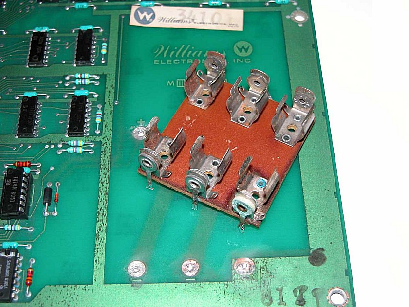
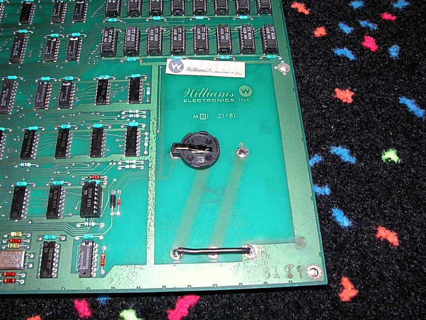
up but going straight to the bookkeeping screen. As it turns
out, the original battery holder was corroded so it was replaced with a
lithium ion battery kit. The pictures show the original crusty
battery holder and the new clean lithium ion battery holder.
|
 |
With
the battery kit installed I was able to play the game but there was no
sound. The game was found to have a bad 6808 CPU on the sound
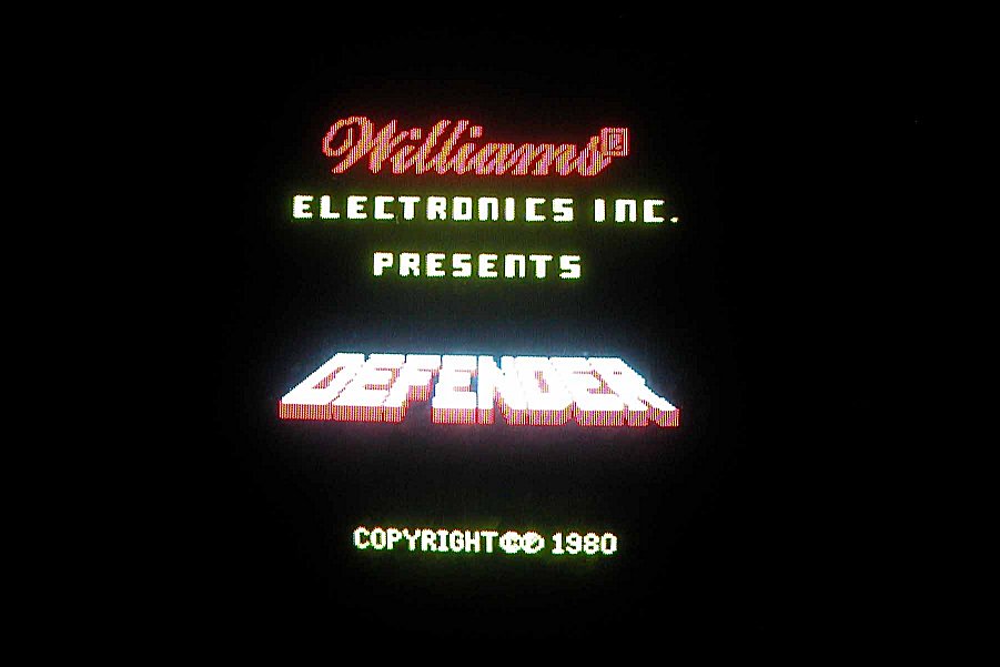
board. Once that was replaced - I FINALLY HAD DEFENDER RUNNING! I
was never
so happy to finally see the screen shown in the picture to
the left. After a long series of tough repairs...this game
is still just as TOUGH to play as I remember!
|
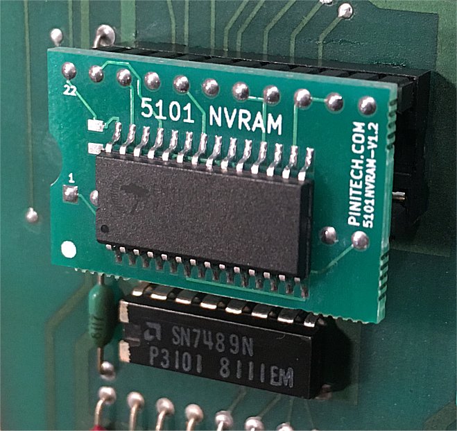 |
The lithium ion battery battery, that had powered the high score circuit since the game was restored in 2009, finally died. Instead of replacing the battery with another battery I decided to go with a 5101 NVRAM module. There are several to choose from but I selected the one from Pinitech, which is available here. The 5101 CMOS chip is removed from 1E and a socket is installed. The NVRAM module is then simply plugged into the socket. |
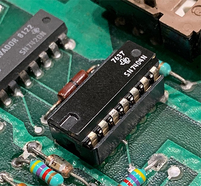 |
Defender had another issue worth noting. Upon power up the game worked fine but all of the game settings were maxed out (number of ships, etc.). Upon entering bookkeeping through the coin door switches I was unable to make any changes to the settings. When hitting the high score switch the screen would only ‘blink’ and no change would be made to the settings. I thought for sure it was going to be a connection issue but I tested the coin door switch – checked fine. I then followed the low signal generated by the switch through connector 2J3 (pin 4-PA3) on the ROM board all the way to IC22. I found no issues. So then I went to the CMOS RAM circuit knowing the R/W function is disabled when the coin door is closed. When the coin door is open it allows changes to be made. The input signal from the coin door circuit is through the 1J5 connector (pin1) and was stuck low in both the open and closed coin door positions! So that was certainly a FAULT! Interesting enough a quick check at the first IC in this circuit (5B – 7404 TTL Pin3) showed a stuck low signal as well. The resistor (R32) and capacitor (C61) tested fine out of circuit. However, a quick check of pin 1 of the 1J5 connector showed it had a 1.0ohm short to the 5.0VDC line! So that pointed to the 5B 7404 being bad. I removed the chip and socketed it and installed a new 7404. Outstanding! Short removed and now I’m able to change the settings on the bookkeeping screen with the high score switch! |
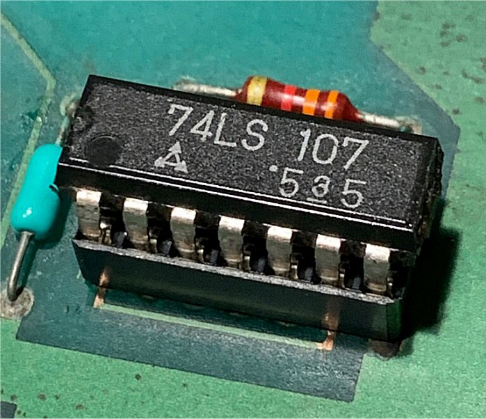 |
Recently, the game went completely dead with no video output (not even a fixed rug screen) and only one bank of RAM (Z1) showing signs of life. The four LED’s were a single flash at power up and remained off offering no diagnostic help. It turns out there was a failure in the external clock circuit resulting in a 1.5 MHz clock signal being supplied to the 6809E instead of the required 1.0 MHz. The schematic confirmed at location 7R a 4 MHz signal is supposed to be present and was measuring 6 MHz. Not good! 7R is a 74LS107, which was socketed/replaced. A corroded trace found under the IC, which connected pins 3 and 8, was also fixed. Once repaired 7R pin 6 was now supplying the correct signal of 4 MHz and Defender was back to life! |