|
Gun
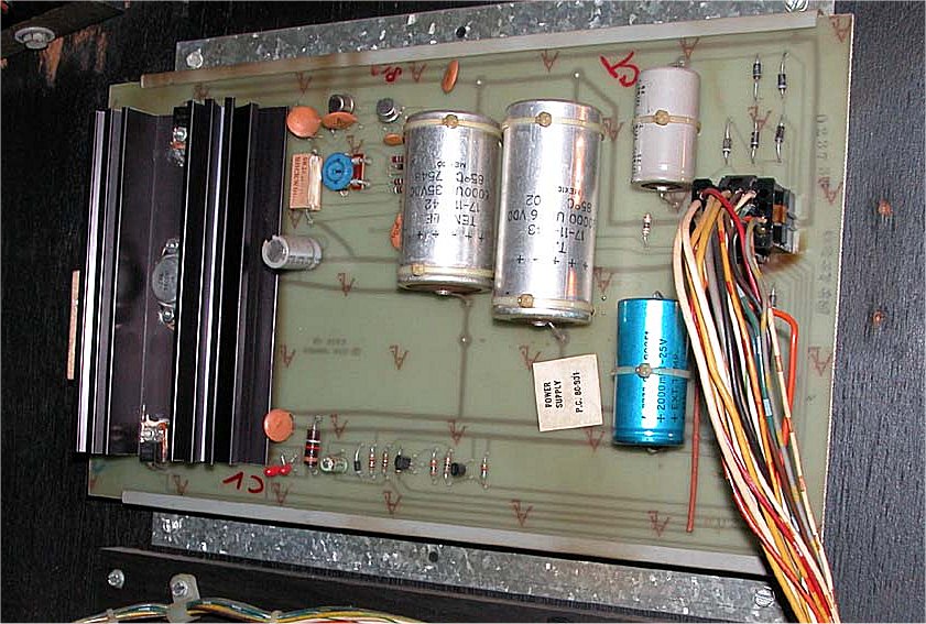
Fight arrived in the Repair Station in very good condition but blew a
fuse upon being turned on. Usually this is indicative of a problem with
the power supply board. I removed the board and reflowed a number of
bad solder points. I reinstalled the board and again turned the game
on. The game blew a fuse immediately. I needed to isolate the problem
to a major component so I disconnected the power transformer, power
supply board, PCB and chassis. I put in a new fuse, plugged the game in
and began reconnecting each component one at a time. Everything was
fine util I connected the PCB. The fuse blew as soon as the PCB was
connected. Even theugh I was about to run out of fuses, I had at least
isolated the problem!
|
|
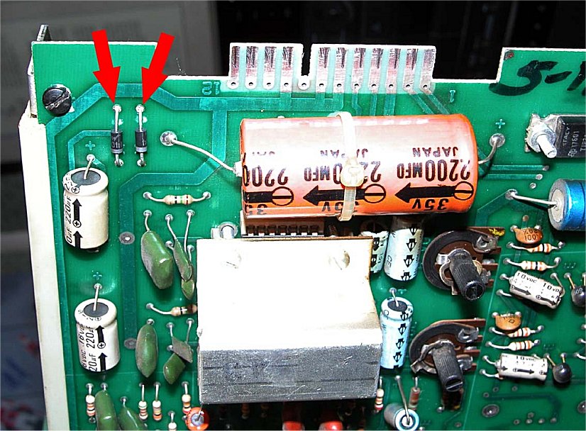
The
PCB was diagnosed and two diodes on the daughter board were found to be
bad. The diodes were replaced and the PCB was put back in the game. I
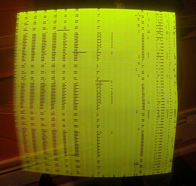
crossed my fingers as I turned the game on. The game no longer blew a
fuse but nothing on the screen was recognizable.
|
|
I felt the
display problem may be caused by ar ROM error so I removed, cleaned and
reseated all the ROMs as well as the Intel 8080 CPU. I put the PCB back
in the game and once again turned it on....
|
|
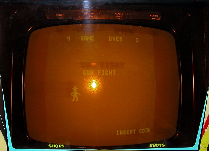
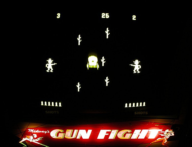
Success! Sort of. The screen now had a picture but it was noticeably
reduced in size. Since I had a display, I was finally able to play the
game! The game coined up and worked fine but there was no sound.
|
|
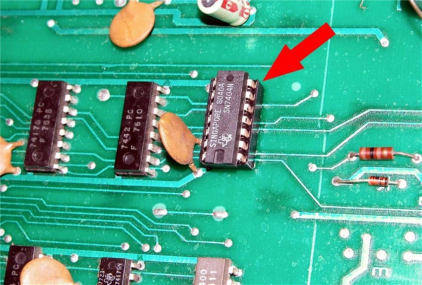
Checking the PCB carefully, I noticed that one chip appeared to have
been replaced in the past. Figuring this would be a good place to
start, I checked it with my logic probe. It was bad! Since the
chip appeared to have gone bad at least once before, I figured I would
make it a socketed chip so if it went bad in the future it could be
easily replaced. The chip was an SN7404N located at H6. I reinstalled
the PCB and tried the game. Yes! I now had sound.
|
|
Now it was time to work on the display
issue. The monitor was a Motorola XM701, which was
a stalwart of the early B & W games. Checking the schematic
indicated that I should have 73VDC on the B+ circuit. I only had 48VDC.
Turning the voltage regulator failed to increase the voltage. Studying
the schematic, I narrowed the problem down to four components within
the power supply circuit. I had planned on buying all new components
but cross referencing the original Motorola part numbers proved to be
quite a task. I was eventually put in contact with a collector in
Kentucky who had the parts that I needed. I installed a 33V, 1W Zener
diode and tested the game. Yipee! Fixed. OK partner, draw!!
|


 Gun
Fight Repair Log
Gun
Fight Repair Log


